


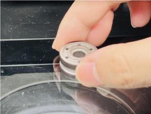
How can the inner diameter, outer diameter, and width of a bearing be measured accurately?
As a core component of mechanical transmission systems, the geometric dimensional accuracy of bearings directly impacts equipment operational stability, service life, and transmission efficiency. Precise measurement of critical bearing dimensions requires clearly defined measurement criteria, selection of appropriate equipment, and strict adherence to standardized operating procedures.

I. Bearing Measurement Requirements

1. Inner Ring Diameter (d): The nominal diameter of the inner bore of the bearing inner ring, serving as the critical dimension for mating with the shaft (rotating shaft). This ensures an interference/transition fit between the inner ring and shaft, preventing “slippage” or “seizing” during operation.
2. Outer Ring Dimension (D): The nominal diameter of the outer ring's circumference, serving as the critical dimension for mating with the bearing housing. It ensures a clearance/transition fit between the outer ring and housing, balancing installation convenience with operational stability.
3. Width (B/T): The overall thickness of the bearing along its axial direction. This dimension accommodates the axial installation space within the equipment, preventing excessive axial clearance that could cause vibration or abnormal noise.
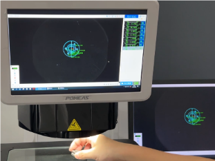
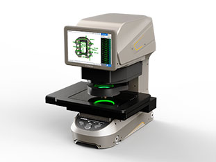
II. Measuring Equipment: POMEAS Image Measuring Instrument
1. Ultra-high precision: Measurement accuracy reaches 2.5μm (micrometers), far exceeding traditional calipers (accuracy 0.02mm) and micrometers (accuracy 0.001mm), meeting the measurement requirements for precision bearings (such as P5 and P4 grades);
2. One-Click efficient measurement: Pre-programmed to automatically identify measurement targets on bearing inner rings, outer rings, and widths, eliminating manual point-by-point calibration and significantly reducing operational errors and measurement time;
3. Non-Contact measurement: Utilizes optical imaging principles to prevent scratches or deformation on bearing surfaces (especially precision raceways) caused by traditional contact methods (e.g., micrometers);
4. Automated data processing: Automatically records measurement data (e.g., maximum/minimum inner diameter, outer diameter roundness deviation), generates reports, and enables export for quality traceability and statistical analysis.
Suitable for batch bearing inspection (such as production line sampling and factory quality control), dimensional verification of high-precision bearings (such as machine tool spindle bearings and automotive transmission bearings), and compatible with measurement requirements for various bearing types (deep groove ball bearings, cylindrical roller bearings, angular contact ball bearings).
III. Key Operational Steps for Precise Measurement

Phase 1: Preliminary Preparation (Ensuring Accurate Measurement Reference)
① Equipment Calibration: After powering on the device, perform “linear calibration” on the measuring instrument using standard gauge blocks (e.g., 10mm, 20mm, 50mm high-precision gauge blocks) to ensure measurement accuracy along the X-axis, Y-axis (planar direction), and Z-axis (height direction) meets the 2.5μm standard; Clean the measurement platform and optical lenses to prevent dust or oil contamination from affecting imaging clarity (gently wipe with a lint-free cloth dampened with anhydrous ethanol).
② Bearing Pre-treatment: Remove rust-preventive oil and impurities from the bearing surface (use compressed air to blow away surface dust). For new bearings, verify they have not been deformed during transportation. For reconditioned bearings, clean off surface wear debris to prevent misjudgment of dimensional deviations.
Phase 2: Measurement Program Programming (Only required for initial measurement)
① Positioning the Standard Bearing: Place a standard bearing of the same model (a calibrated part with known accurate dimensions) at the center of the measurement platform. Ensure the bearing axis is perpendicular to the platform plane (a square may be used for positioning assistance).
② Setting Measurement Targets: Launch the image measurement software and adjust the lens focus to achieve clear imaging of the bearing's inner ring, outer ring, and width edges. Manually select “Inner Diameter Measurement Points” (choose 4-6 evenly spaced points along the inner bore circumference, covering different quadrants), “Outer Diameter Measurement Points” (same logic as inner diameter, avoiding points on the same radial line), and “Width Measurement Points” (select 2 symmetrical points at each end of the width); The software automatically calculates the theoretical values for inner diameter, outer diameter, and width of the standard bearing, saves them as a “Measurement Template,” and completes programming.
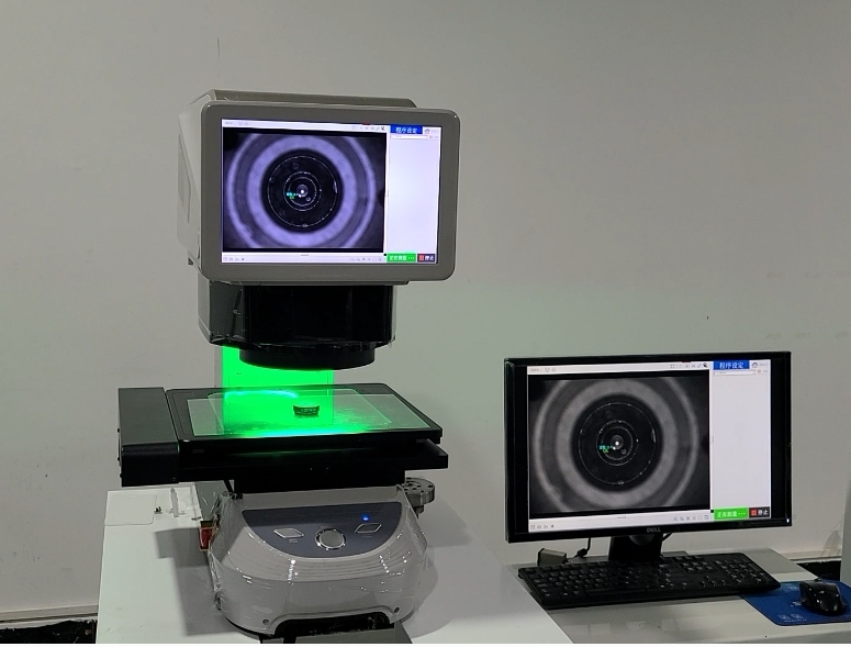
Phase 3: Batch “One-Click Measurement” (Core Operation)
① Place test bearing: Replace the standard bearing with the test bearing and position it in the same area on the measurement platform (alignment aids like locating pins and scale lines ensure consistent placement each time).
② Initiate one-click measurement: Click the software's “One-Click Measurement” button. The device automatically moves the lens to capture image data of the inner ring, outer ring, and width according to the preset template. The software calculates dimensional deviations in real-time (e.g., difference between actual and nominal inner diameter, outer diameter roundness error) and displays an “OK/NG” judgment on the interface (requires pre-set tolerance range).
③ Data logging and traceability: Upon completion, the software automatically saves individual data sets. These can be exported in bulk to Excel/CSV format, recording bearing ID, measurement time, and dimensional values. Non-conforming parts are marked and stored separately for subsequent analysis of deviation causes (e.g., tool wear, heat treatment distortion).
Phase 4: Post-Measurement Calibration (Ensuring Equipment Stability)
After measuring 50-100 bearings, reinsert a standard bearing for “calibration” to verify that the measuring instrument's accuracy has not drifted. At the end of each day's measurements, before shutting down the equipment, clean the platform and lens again, cover with a dust cover, and prevent moisture exposure.

Product recommendation
TECHNICAL SOLUTION
MORE+You may also be interested in the following information
FREE CONSULTING SERVICE
Let’s help you to find the right solution for your project!

 ASK POMEAS
  PRICE INQUIRY
  REQUEST DEMO/TEST
  FREE TRIAL UNIT
  ACCURATE SELECTION
 - APPICATION CASE
- RESOURCE CENTER
- DOWNLOAD CENTER
SOLUTIONS SUPPORT
- ZOOM LENS SELECTION TOOL
- TELECENTRIC LENS SELECTION TOOL
- FA LENS SELECTION TOOL
- ZOOM RATIO TABLE
- CERTIFIED MODEL
SELECTION TOOL
- WHY POMEAS
- FAQ
- PRIVACY POLICY
- TERMS OF USE
- DELIVERY & RETURN POLICY
CUSTOMER CARE
 ADDRESS
Add.:No.68, Chongwei Road, Baizhoubian, East district, Dongguan, China, 523000
CONTACT
 Tel:+ 86-0769-2266 0867
 Fax:+ 86-0769-2266 0867
 E-mail:marketing@pomeas.com

Wechat QR code
Software Copyright :2021SR0176001 抄袭必究, 技术支持:誉新源科技