


Troubleshooting Common Issues with Telecentric Measurement System
Telecentric Measurement Systems have gained widespread popularity among manufacturers across numerous industries due to their ability to perform real-time dimensional measurements, compact size, and ease of integration, making them essential tools in production inspection processes. However, in practical applications, many users harbor certain misconceptions about these devices. Below, we provide detailed explanations for several common issues.


Q1 Can blind holes be measured?

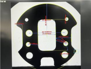
Telecentric Measurement Systems cannot measure blind hole dimensions; they can only measure through-hole dimensions. This limitation primarily stems from their measurement principle, which requires projecting the product's image onto a screen and analyzing the image information displayed to obtain dimensional data. For blind holes, since their bottoms are closed, the instrument cannot fully capture the image information of their internal structure, making accurate dimension measurement impossible. Through holes, however, are fully penetrated, allowing the image to clearly display both their internal and external contours, enabling precise dimension measurement.
Q2 Can 3D profiles be measured?

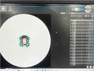
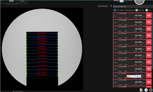
Telecentric Measurement System primarily focuses on product appearance dimensions, specifically the measurement of planar dimensions, and does not possess three-dimensional contour measurement capabilities. Its operational mode is based on two-dimensional image acquisition and analysis. By processing the projected image of the product onto a plane, it derives planar dimensional parameters such as length, width, and diameter. Three-dimensional contour measurement, however, involves capturing shape and dimensional information across all three spatial dimensions of an object. This requires more sophisticated measurement technologies and equipment, such as laser scanners and coordinate measuring machines (CMMs). These devices acquire the coordinates of various points on an object's surface within three-dimensional space, thereby constructing a three-dimensional model of the object to achieve three-dimensional contour measurement.
Q3: What is the maximum product size supported for measurement?

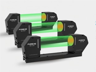
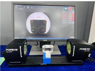
The maximum product dimensions supported by different specifications and models of online image measuring instruments vary. Taking the three specifications of the HM series as an example:
1. HM-1040: This model of Telecentric Measurement System supports measuring products up to 40mm in size. It is suitable for measuring relatively small components and plays a crucial role in production inspection for precision electronic components and small mechanical parts.
2. HM-1065: This model supports measurements up to 65mm. Compared to the HM-1040, its expanded measurement range accommodates slightly larger products, making it suitable for inspection in certain medium-scale industrial applications.
3. HM-1120: This model offers the largest measurement range within the HM series of Telecentric Measurement Systems, supporting products up to 120mm. For larger components such as substantial mechanical structural parts and automotive components, the HM-1120 delivers precise dimensional measurement services.
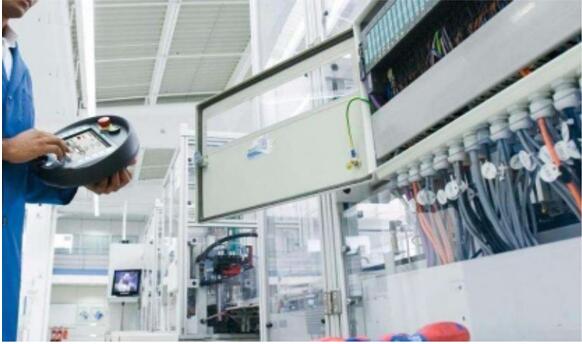
Q4: Can measurement data be directly integrated with production systems (such as MES/ERP)?

Modern online telecentric measurement systems are commonly equipped with standardized data interfaces (such as OPC UA, Modbus TCP, and direct database connectivity), enabling seamless integration with MES, ERP, QC, and other systems. Users can achieve data flow through the following methods:
1. Real-time Transmission: Measurement results automatically upload to the production system, triggering quality judgments or process adjustments;
2. Traceability Management: Generates traceable inspection reports by linking product batch numbers, measurement times, operators, and other information;
3. Statistical Analysis: System automatically generates key metrics such as CPK and defect rates to support production optimization.
4. Equipment Integration: Also supports robotic arm integration to achieve a fully automated “measure-sort-feedback” workflow.
Q5 Can transparent or reflective materials be measured accurately?

Handling requires case-by-case consideration. Traditional equipment measuring transparent materials (such as glass or acrylic) or highly reflective surfaces (such as mirrored metal) is prone to light interference, resulting in blurred edges.
Q6 What is the equipment calibration cycle?


It is generally recommended to calibrate every three months.,however, the specific cycle must be determined based on usage frequency and environmental conditions.
Product recommendation
TECHNICAL SOLUTION
MORE+You may also be interested in the following information
FREE CONSULTING SERVICE
Let’s help you to find the right solution for your project!
 ASK POMEAS
  PRICE INQUIRY
  REQUEST DEMO/TEST
  FREE TRIAL UNIT
  ACCURATE SELECTION
 - APPICATION CASE
- RESOURCE CENTER
- DOWNLOAD CENTER
SOLUTIONS SUPPORT
- ZOOM LENS SELECTION TOOL
- TELECENTRIC LENS SELECTION TOOL
- FA LENS SELECTION TOOL
- ZOOM RATIO TABLE
- CERTIFIED MODEL
SELECTION TOOL
- WHY POMEAS
- FAQ
- PRIVACY POLICY
- TERMS OF USE
- DELIVERY & RETURN POLICY
CUSTOMER CARE
 ADDRESS
Add.:No.68, Chongwei Road, Baizhoubian, East district, Dongguan, China, 523000
CONTACT
 Tel:+ 86-0769-2266 0867
 Fax:+ 86-0769-2266 0867
 E-mail:marketing@pomeas.com

Wechat QR code
Software Copyright :2021SR0176001 抄袭必究, 技术支持:誉新源科技