


Guide to Selecting Wire Harness Terminal Dimension Inspection Equipment
I. Requirements For Wiring Harness Terminal Dimensions

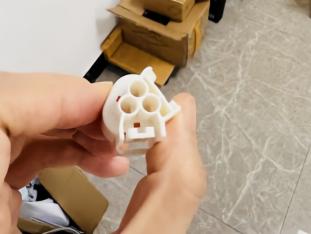
1. Appearance and fitting dimensions of the terminal body
When not crimped, the external dimensions must be strictly controlled in accordance with the engineering drawings. This primarily includes the overall length, width and thickness, to ensure that the component can be fitted smoothly into the plastic-cased rubber socket. For the pin section, particular attention must be paid to controlling the pin diameter, pin length and the centre-to-centre distance (pitch) between adjacent pins, to prevent ‘failure to mate’ or short circuits during assembly caused by spacing deviations. In addition, the dimensions of the locking mechanism’s recesses and the opening of the spring tabs must be inspected to ensure that the retaining force after assembly complies with specifications.
2. Key dimensions of crimped terminals (core quality control points)
-
Conductor crimp height: This is the most important parameter, as it is directly related to contact resistance and pull-out force. Tolerances are typically required to be within ±0.03 mm to 0.05 mm.
-
Conductor crimp width: Determined by the physical dimensions of the die; regular spot checks are required to ensure the die has not worn out.
-
Bellmouth: The front and rear ends of the crimped terminal must feature a slight bell-shaped opening to prevent sharp metal edges from cutting the copper strands; this is typically required to be greater than 0.05 mm and less than 0.4 mm.
-
Burrs and Exposed Core Wire: The height of any burrs formed at the base of the crimp must not exceed the thickness of the material, and the copper strands of the core wire should protrude slightly from the front edge of the crimped area, but must not be so long as to cause a short circuit.
II. Challenges in Inspecting the Dimensions of Wiring Harness Terminals


1. Reflective Interference on Metal Surfaces
Terminals are typically tin-plated, gold-plated or silver-plated, and their surfaces are highly reflective. During optical measurement, this can easily cause glare or overexposure, making it difficult for the camera to capture the true edge contours and resulting in measurement errors.
2. Microscopic Dimensions and Three-Dimensional Geometry
Modern electronic connectors are becoming increasingly miniaturised, with pin pitches reduced to 0.3 millimetres or even smaller—dimensions that traditional callipers cannot measure. Furthermore, the coplanarity of the pins (whether all pin tips lie in the same plane) and height differences constitute three-dimensional spatial data, which are difficult to obtain using standard two-dimensional measurement methods.
3. Concealed Nature of Crimped Cross-Sections
Crimp height can be measured using a height gauge; however, to assess whether the crimp is ‘solid’ (i.e. whether the copper wire has been compacted and whether there are any voids), the cross-section must be examined. This involves destructive cutting, grinding and microscopic analysis—a complex and time-consuming process that makes 100 per cent inspection difficult to achieve.
4. The conflict between production line cycle time and precision
Production lines operate at an extremely fast pace; manual measurement using a tool microscope is inefficient and highly subjective, easily becoming a bottleneck in production capacity, whilst also making it difficult to achieve digital traceability of data.
III. Recommended Measuring Equipment
1. One-Button Flash Tester

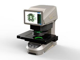
Suitable for 100 per cent inspection on production lines. By placing multiple terminals in any arrangement on the stage, the equipment can measure dozens of dimensions in a single pass within a matter of seconds, offering extremely high efficiency. It is particularly well-suited to the rapid screening of high-volume, small-sized terminals.
2. 3D Line Laser Profiler
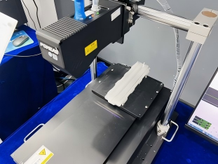

Suitable for online automated inspection. Installed behind the crimping machine, it utilises the principle of laser triangulation to scan the three-dimensional contour of the terminals without contact, monitoring pin coplanarity and height in real time, and automatically rejecting defective products.
Product recommendation
TECHNICAL SOLUTION
MORE+You may also be interested in the following information
FREE CONSULTING SERVICE
Let’s help you to find the right solution for your project!
 ASK POMEAS
  PRICE INQUIRY
  REQUEST DEMO/TEST
  FREE TRIAL UNIT
  ACCURATE SELECTION
- APPICATION CASE
- RESOURCE CENTER
- DOWNLOAD CENTER
SOLUTIONS SUPPORT
- ZOOM LENS SELECTION TOOL
- TELECENTRIC LENS SELECTION TOOL
- FA LENS SELECTION TOOL
- ZOOM RATIO TABLE
- CERTIFIED MODEL
SELECTION TOOL
- WHY POMEAS
- FAQ
- PRIVACY POLICY
- TERMS OF USE
- DELIVERY & RETURN POLICY
CUSTOMER CARE
 ADDRESS
Add.:No.68, Yongwei Road, Baizhoubian, Dongcheng District, Dongguan, China,523000
CONTACT
 Tel:+ 86-0769-2266 0867
 Fax:+ 86-0769-2266 0867
 E-mail:marketing@pomeas.com

Wechat QR code

Software Copyright :2021SR0176001 抄袭必究, 技术支持:誉新源科技