


In the field of industrial machine vision, one often encounters a type of lens that is robust and elongated, resembling a gun barrel; these are commonly referred to in the industry as ‘barrel lenses’. Such lenses are typically used in applications such as high-precision inspection and large-format scanning, but many users encounter a series of tricky problems when using them for the first time.


I. What is a ‘cannon-barrel lens’?
The term ‘cannon-barrel lens’ is not a strict optical classification, but rather a figurative term for a class of industrial lenses characterised by a long barrel, a large image plane and high resolution.
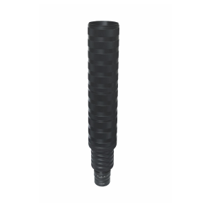

1. Large-format coverage: Capable of accommodating camera sensors with an extremely large imaging circle, such as line-scan cameras and large-format area-scan cameras (e.g. full-frame, medium-format, and even 6K, 8K and 18K line-scan cameras), ensuring that effective pixels are captured from the centre to the edges.
2. Long overall optical length: In order to accommodate large sensor sizes, achieve high resolution and control aberrations, the optical design is often complex, comprising numerous lens groups; consequently, the barrel is naturally elongated, giving it an appearance reminiscent of a gun barrel.

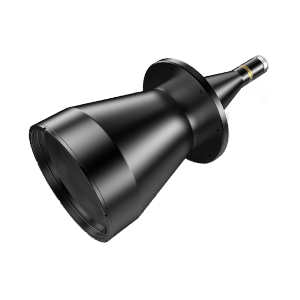
3. High-precision optical performance: Many large-aperture lenses are telecentric (particularly object-side or image-side telecentric designs), or are specifically designed as large-sensor prime lenses, with the aim of achieving low distortion, high uniformity and extremely high resolution.
II. What problems can arise in the practical application of barrel lenses? What are the common issues?
Although the cannon-barrel lens offers impressive performance, its precision and bulky size also present challenges for on-site integration.

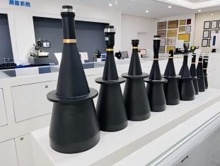
1. Loose Fitting and Off-Centre Shaft Alignment
Large-bore lenses often weigh considerably more than standard C-mount lenses, with some weighing as much as one or two kilograms. If the load is borne solely by the cantilevered lens mount threads, the mount is highly susceptible to developing slight play over prolonged use or in vibrating environments. Once play occurs, the entire optical axis shifts, resulting in one side of the image being sharp whilst the other is blurred, and causing the measurement reference to drift.
A more subtle issue is that stress relief in the fasteners causes the lens to become misaligned with the camera’s sensor plane; even if this is imperceptible to the naked eye, it can introduce significant ‘perspective error’ in micrometre-level measurements. Therefore, it is essential to provide the lens with an independent support structure or a sturdy lens mount, and to regularly calibrate the optical axis.
2. Straylight and Ghosting Interference
The longer optical path inside a long lens barrel poses a severe challenge in terms of stray light control. Inadequate anti-reflective treatment on the internal threads of the barrel, defects in the coating or ink application on the edges of the lens elements, or strong external light leaking in through gaps in the barrel can all result in localised spots on the image, reduce overall contrast, or even produce noticeable ghosting.
In practical use, users often notice a hazy halo in the centre of the image or strange reflections at the edges; this is frequently due to inadequate anti-glare design in the lens itself, or the failure to fit a suitable lens hood to the front of the lens. High-quality super-telephoto lenses must undergo thorough anti-glare treatment before leaving the factory, including precision ink application, multi-stage anti-glare threading and blackening of the lens edges.
3. Image Quality Degradation at the Edges and Image Field Non-uniformity
Telephoto lenses are often used to ‘squeeze’ a large image field; however, the light rays at the edges of the field of view are highly oblique, making these areas the most difficult to correct for aberrations. Whilst some lenses offer astonishing resolution at the centre, resolution drops sharply at the corners, accompanied by field curvature and astigmatism, resulting in blurred imaging at the edges.
Another associated issue is brightness uniformity (vignetting). When used with large sensor formats, even if the lens’s image circle is sufficiently large to cover the sensor, the physical cosine-fourth law means that the edges will be slightly darker than the centre. This vignetting becomes even more pronounced if the optical design does not adequately correct for astigmatism, or if the flange distance is incorrectly matched. When using large-aperture lenses, it is advisable to carefully verify that the image circle not only ‘covers’ the sensor but also allows for sufficient design margin, in order to ensure consistent image quality across the entire frame.
4. Focus Sensitivity and Depth of Field Limitations
Telephoto lenses are often paired with high-resolution cameras featuring small pixel sizes; such systems have an extremely low tolerance for focus shifts. Even minor mechanical errors or thermal expansion and contraction caused by temperature changes can cause the optimal focal plane to drift away from the target surface, resulting in overall image softness.
At the same time, a large sensor size and high magnification often result in a high numerical aperture; whilst maintaining high brightness, this leads to a very shallow depth of field. In inspection scenarios involving undulating terrain or vibrations, this makes localised blurring highly likely. In addition to locking the focusing mechanism and selecting an optical system with thermal drift compensation, the solution requires careful calculation of the depth of field during the design evaluation stage to ensure it falls within the tolerance range.
5. Working distance and mechanical interference conflicts
In order to achieve a large image sensor, barrel-type lenses sometimes require an increased working distance (WD); however, within the confined space of compact equipment, this can present mechanical layout challenges. The lens’s substantial diameter may also physically interfere with adjacent light sources or fixtures, rendering an otherwise perfect optical path design impossible to fit during on-site assembly. Obtaining precise 3D contour drawings of the lens in advance and creating a digital model to simulate the assembly is the only way to avoid rework.
Product recommendation
TECHNICAL SOLUTION
MORE+You may also be interested in the following information
FREE CONSULTING SERVICE
Let’s help you to find the right solution for your project!
 ASK POMEAS
  PRICE INQUIRY
  REQUEST DEMO/TEST
  FREE TRIAL UNIT
  ACCURATE SELECTION
- APPICATION CASE
- RESOURCE CENTER
- DOWNLOAD CENTER
SOLUTIONS SUPPORT
- ZOOM LENS SELECTION TOOL
- TELECENTRIC LENS SELECTION TOOL
- FA LENS SELECTION TOOL
- ZOOM RATIO TABLE
- CERTIFIED MODEL
SELECTION TOOL
- WHY POMEAS
- FAQ
- PRIVACY POLICY
- TERMS OF USE
- DELIVERY & RETURN POLICY
CUSTOMER CARE
 ADDRESS
Add.:No.68, Yongwei Road, Baizhoubian, Dongcheng District, Dongguan, China,523000
CONTACT
 Tel:+ 86-0769-2266 0867
 Fax:+ 86-0769-2266 0867
 E-mail:marketing@pomeas.com

Wechat QR code

Software Copyright :2021SR0176001 抄袭必究, 技术支持:誉新源科技