


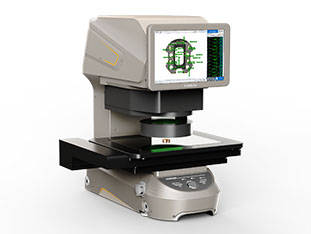
Flash measuring instruments are often referred to as “one-click” imaging measuring instruments. Their key feature is that, once the workpiece is placed and the measurement is triggered, the software automatically recognizes the contour and provides dimensional results. They are suitable for rapid inspection of two-dimensional dimensions, as well as batch sampling and 100% inspection; however, different models vary significantly in terms of field of view, accuracy, lighting, software, and automation capabilities. When selecting a model, it is recommended to base your decision on actual measurement tasks rather than relying solely on advertised specifications.

I. First, determine what to measure and how to measure it

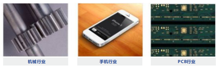
Before selecting a model, organize the list of parts: size range, thickness, material, color, surface reflectivity, and whether features such as contours, hole positions, spacing, angles, or circle diameters need to be measured. Transparent parts, reflective parts, black parts, flexible parts, and parts prone to deformation have different requirements for light sources and clamping methods. You must also confirm whether sampling or 100% inspection is required, what the drawing tolerances are, and how many parts are measured daily. Accuracy requirements should be determined by the tolerances; simply allow for a measurement margin—there is no need to blindly pursue the highest accuracy.
II. Accuracy Depends on Repeatability and Indication Error

Resolution and pixel count are just the basics; repeatability, indication error, lens distortion, and platform accuracy deserve greater attention. In batch inspection, repeatability directly affects the stability of inspection results. When inquiring about parameters, consider the test conditions: which reference parts are used, at what temperature, how many measurements are taken, and which areas of the field of view are covered. It is generally recommended that the measurement system error not exceed one-tenth to one-third of the workpiece’s tolerance band; specific requirements should be evaluated based on quality standards. A balance is often needed between accuracy and field of view: a wide field of view facilitates overall imaging, while a narrow field of view allows for detailed observation; stitching measurements expand the coverage area but increase cycle time.
III. The field of view, travel range, and clamping must be compatible with the workpiece

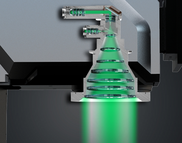
The dimensions and placement of the workpiece determine the choice of field of view. Multiple small workpieces can be placed at once to improve efficiency; large workpieces may require stitching or moving the platform. It is also important to consider fixture space, loading and unloading space, and variations in workpiece thickness. When there are significant differences in thickness, the ease of focusing can affect the user experience. Stable clamping and smooth loading and unloading often have a greater impact on daily use than having a few additional parameters.
IV. Lighting should complement the materials, rather than simply aiming for variety

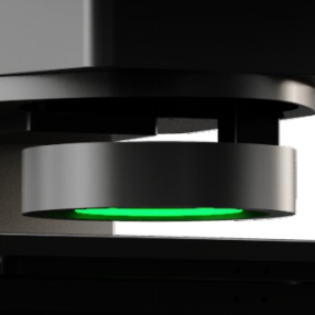
Backlighting is suitable for contour and through-hole measurements, while surface lighting or coaxial lighting is suitable for surface features. Reflective, transparent, rough, and dark materials require different lighting combinations. When selecting a system, verify the lighting setup using actual samples to ensure that edges are sharp and features are consistently recognized. The ease of adjusting the lighting configuration and the ability to save presets also affect changeover efficiency.
V. Software and Automation Capabilities Determine Usability

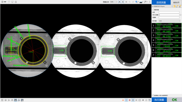
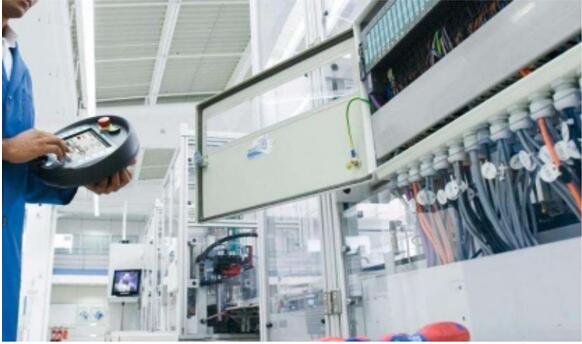
Consider whether the software is intuitive, capable of automatic recognition, and supports batch reporting, CAD import/export, data analysis, and permission management. If integrating with a production line, verify the input/output interfaces, PLC communication, and the system’s ability to interface with databases or production systems. Practical metrics include operator training costs, the speed of recipe switching, and the clarity of error messages. A wealth of features does not necessarily equate to usability; the ability to reliably perform current tasks while allowing for easy expansion is more critical.
VI. Count the Beats Throughout the Entire Process
Measuring cycle time involves more than just taking photos and calculating time; it also includes loading and unloading, focusing, inspection, and reporting. When inquiring about cycle time, clarify whether it refers to a single feature or the measurement of an entire part. For batch 100% inspection, calculate both loading/unloading and labor time. Automated loading/unloading and multi-station turntables can improve efficiency, but the investment and maintenance costs must also be evaluated.
VII. Don’t Overlook the Environment, Data, and After-Sales Service
Changes in workshop temperature, vibration, dust, and lighting can affect measurement performance. Laboratory models and workshop models may differ in terms of structural protection and stability design; select the appropriate model based on the installation environment. For data traceability, consider report formats, historical data export capabilities, and calibration reminders. When budgeting, calculate the total cost of ownership, including equipment, fixtures, software modules, training, maintenance, and calibration. It is recommended to research after-sales response times, spare parts availability, and application support in advance.
VIII. Make a determination based on test results using sample parts
Prepare samples that cover the upper and lower tolerance limits, as well as different materials and surface finishes, and conduct test runs on-site or via video. Focus on repeatability, cycle time, operating procedures, and report output. Having multiple companies test the same batch of samples provides more valuable insights than simply reviewing a list of specifications.
Product recommendation
TECHNICAL SOLUTION
MORE+You may also be interested in the following information
FREE CONSULTING SERVICE
Let’s help you to find the right solution for your project!
 ASK POMEAS
 PRICE INQUIRY
 REQUEST DEMO/TEST
 FREE TRIAL UNIT
 ACCURATE SELECTION

- APPICATION CASE
- RESOURCE CENTER
- DOWNLOAD CENTER
SOLUTIONS SUPPORT
- ZOOM LENS SELECTION TOOL
- TELECENTRIC LENS SELECTION TOOL
- FA LENS SELECTION TOOL
- ZOOM RATIO TABLE
- CERTIFIED MODEL
SELECTION TOOL
- WHY POMEAS
- FAQ
- PRIVACY POLICY
- TERMS OF USE
- DELIVERY & RETURN POLICY
CUSTOMER CARE
 ADDRESS
Add.:No.68, Yongwei Road, Baizhoubian, Dongcheng District, Dongguan, China,523000
CONTACT
 Tel:+ 86-0769-2266 0867
 Fax:+ 86-0769-2266 0867
 E-mail:marketing@pomeas.com

Wechat QR code

Software Copyright :2021SR0176001 抄袭必究, 技术支持:誉新源科技