


When designing vision systems for precision measurement or defect detection, high-resolution telecentric lenses cannot simply be fitted as standard components. The optical parameters of the lens must be precisely matched to the industrial camera, the object being measured and the mechanical structure; otherwise, even the finest lens design will struggle to produce reliable results.

I. Matching Resolution and Camera Pixel Size
Optical resolution reflects the smallest feature spacing that a lens can resolve. When selecting a lens, the primary consideration is to ensure that the lens’s resolving power is compatible with the camera’s pixel size. Typically, the lens’s cut-off frequency on the image side must exceed the Nyquist frequency determined by the camera sensor. Put simply, if the camera’s pixel size is 3.45 μm, the corresponding spatial frequency is approximately 145 lp/mm; the MTF value of the selected high-resolution telecentric lens at this frequency should be sufficiently high. If the lens resolution is insufficient, a camera with large pixels or a high pixel count will only produce a blurred, magnified image; conversely, if the lens has excessive resolving power, the image will be sharp but may incur unnecessary costs. The first step in the selection process is to determine the required optical performance of the lens based on the pixel size.
II. Magnification and Field of View
High-resolution telecentric lenses are typically designed with fixed magnifications, such as 0.5×, 1× and 2×. The formula for calculating the field of view is: Field of view = Effective size of the camera sensor ÷ Magnification. When measuring a circular component with a diameter of 20 mm, if a 1-inch sensor-size camera (with a sensor diagonal of approximately 16 mm) is used, a 1× lens will only provide a field of view of approximately 16 mm, which is insufficient to capture the entire component. In this case, the magnification should be adjusted to 0.8× or lower, or a camera with a larger sensor should be used. Conversely, high magnification is required to resolve fine structures in microscopic features, but this will result in a correspondingly reduced field of view. When selecting a lens, it is necessary to find the optimal balance between resolution requirements and the area covered by the inspection.
III. Working Distance and Spatial Layout
The working distance of a telecentric lens is a fixed value, ranging from tens of millimetres to hundreds of millimetres. Before finalising the selection, it is essential to clarify the available mechanical space on the production line or test bench, the configuration of the fixture, and the position of the light source. A short working distance facilitates higher resolution and a compact optical path, but care must be taken to prevent interference between the lens and the workpiece or fixtures. If the inspection process requires the integration of coaxial illumination or a laser displacement sensor, a longer working distance is preferable. At the same time, it is essential to verify that the lens still meets the resolution and distortion specifications at this working distance, to avoid sacrificing accuracy to accommodate space constraints.
IV. The Trade-off Between Depth of Field and Numerical Aperture
The depth of field of a high-resolution telecentric lens directly affects the imaging clarity of features at different height levels. Provided that telecentric characteristics are maintained, the depth of field is determined jointly by the effective F-number, magnification and the permissible straggle spot diameter. When the workpiece under test exhibits significant variations in height, a greater depth of field is required, which typically implies a smaller lens aperture. However, excessively reducing the aperture can lead to a decline in resolution due to diffraction effects. Therefore, it is necessary to select a lens that offers both sufficient depth of field and the required resolving power, taking into account the actual height tolerances of the workpiece and the acceptable range of sharpness; alternatively, a high-resolution telecentric lens specifically optimised for a large depth of field may be chosen.
V. Lens Mounts and Supported Sensor Sizes
The lens mount (e.g. C-mount, F-mount, M42, etc.) must be compatible with the camera’s mechanical interface, and the maximum image circle size for which it is designed must cover the camera’s sensor area. For example, if a high-resolution telecentric lens optimised specifically for a 2/3-inch sensor is mounted on a 1-inch camera, vignetting or a significant deterioration in image quality will occur at the four corners of the image. For applications using large-format, high-pixel-count cameras, a corresponding large-field-of-view, high-resolution telecentric lens should be selected to make full use of the sensor’s total effective pixels. Confirming compatibility with sensor specifications is key to avoiding image circle and edge degradation.
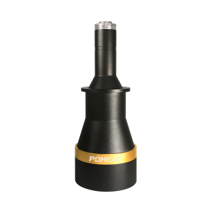
Product recommendation
TECHNICAL SOLUTION
MORE+You may also be interested in the following information
FREE CONSULTING SERVICE
Let’s help you to find the right solution for your project!
 ASK POMEAS
  PRICE INQUIRY
  REQUEST DEMO/TEST
  FREE TRIAL UNIT
  ACCURATE SELECTION
 - APPICATION CASE
- RESOURCE CENTER
- DOWNLOAD CENTER
SOLUTIONS SUPPORT
- ZOOM LENS SELECTION TOOL
- TELECENTRIC LENS SELECTION TOOL
- FA LENS SELECTION TOOL
- ZOOM RATIO TABLE
- CERTIFIED MODEL
SELECTION TOOL
- WHY POMEAS
- FAQ
- PRIVACY POLICY
- TERMS OF USE
- DELIVERY & RETURN POLICY
CUSTOMER CARE
 ADDRESS
Add.:No.68, Yongwei Road, Baizhoubian, Dongcheng District, Dongguan, China,523000
CONTACT
 Tel:+ 86-0769-2266 0867
 Fax:+ 86-0769-2266 0867
 E-mail:marketing@pomeas.com

Wechat QR code
Software Copyright :2021SR0176001 抄袭必究, 技术支持:誉新源科技