


Telephoto Lens Applications: High-Precision Relay Positioning and Bonding Solution
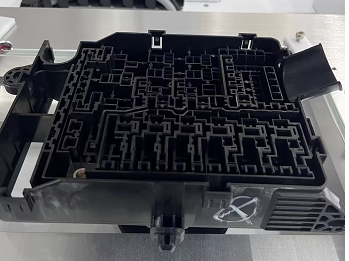
In automated production lines, the precision assembly of relays onto printed circuit boards (PCBs) has always been a critical aspect of quality control. Ensuring sub-micron-level alignment between the relay pins and the positioning holes and marks on the PCB is directly linked to the yield of subsequent soldering operations and the performance of the finished unit.

Testing Challenges and Accuracy Thresholds
The production line requires the vision system to reliably output the centre coordinates and angular deviations of the relay positioning holes at high cycle rates, and to transmit this data in real time to the placement unit. The repeatability of positioning hole detection must be maintained within 0.015 mm, whilst the contour deviation of the auxiliary positioning lines on the board must be better than 0.025 mm. This level of precision poses a dual challenge in terms of distortion control and the algorithm’s ability to withstand interference.
Hardware Selection and Configuration Strategies

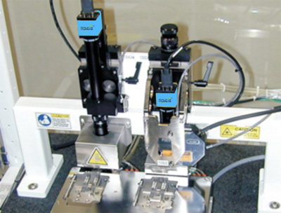
To balance a wide field of view with low distortion, the front-end employs a high-resolution standard telecentric optical path, combined with an industrial-grade Gigabit Ethernet area-scan camera, ensuring that the object-side resolution meets sub-pixel resolution requirements. The illumination module utilises a multi-angle ring-shaped LED light source; by adjusting the light intensity and angle, it creates an ideal grey-scale contrast between the metal surface of the relay and the solder mask layer of the PCB, making the edges of the positioning holes and the positioning lines clearly distinguishable.
Software Algorithm Processing Workflow
1. Image Capture and Pre-processing
An external PLC synchronisation signal triggers the light source to flash, causing the camera to instantly capture an image of the current workstation. The software automatically applies noise filtering and contrast enhancement to the raw image, eliminating interference from ambient stray light and establishing a clean data foundation for subsequent positioning.
2. Feature Localisation and Precise Matching
Built-in professional geometric positioning tools (PatMax series algorithms) employ a strategy combining template matching with edge gradient analysis to rapidly lock onto the centres of positioning holes and positioning lines within the Region of Interest (ROI). These tools are robust against rotation, scaling and changes in brightness, with a single-pixel segmentation accuracy of up to 1/40 pixel, effectively accommodating slight angular deviations in incoming parts.
3. Coordinate Conversion and Data Interaction
Upon completion of the calibration conversion from image space to physical space, the system packages the X, Y and Rz offsets into custom protocol data packets. It communicates in real time with downstream placement controllers via RS232, RS485 or Industrial Ethernet (Ethernet/IP), and supports mainstream fieldbuses such as MODBUS, ensuring that the latency for each alignment command is consistently maintained at the millisecond level.
Product recommendation
TECHNICAL SOLUTION
MORE+You may also be interested in the following information
FREE CONSULTING SERVICE
Let’s help you to find the right solution for your project!
 ASK POMEAS
  PRICE INQUIRY
  REQUEST DEMO/TEST
  FREE TRIAL UNIT
  ACCURATE SELECTION
- APPICATION CASE
- RESOURCE CENTER
- DOWNLOAD CENTER
SOLUTIONS SUPPORT
- ZOOM LENS SELECTION TOOL
- TELECENTRIC LENS SELECTION TOOL
- FA LENS SELECTION TOOL
- ZOOM RATIO TABLE
- CERTIFIED MODEL
SELECTION TOOL
- WHY POMEAS
- FAQ
- PRIVACY POLICY
- TERMS OF USE
- DELIVERY & RETURN POLICY
CUSTOMER CARE
 ADDRESS
Add.:No.68, Yongwei Road, Baizhoubian, Dongcheng District, Dongguan, China,523000
CONTACT
 Tel:+ 86-0769-2266 0867
 Fax:+ 86-0769-2266 0867
 E-mail:marketing@pomeas.com

Wechat QR code

Software Copyright :2021SR0176001 抄袭必究, 技术支持:誉新源科技