


What exactly is an industrial camera? A popular science article explains it all
Industrial cameras are capable of capturing images with precision in factories and laboratories, which are then passed on to computers for image processing and analysis. For this reason, they are widely used in fields such as automated production, quality inspection and visual navigation.

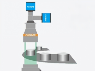
I. What is an Industrial Camera?


Put simply, an industrial camera is a specialised device that converts light signals into structured digital images. Compared to ordinary cameras, it offers high stability and strong resistance to interference, enabling it to operate continuously over long periods in harsh environments such as those involving vibration, dust and high temperatures. More importantly, the image data output by industrial cameras is not subject to excessive enhancement, thereby preserving the most authentic raw information, which facilitates subsequent high-precision algorithmic analysis such as measurement, recognition and positioning. Essentially, it serves as the image sensor front-end in a machine vision system, representing the first step in information acquisition.
II. Classification of Industrial Cameras
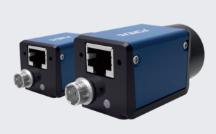
-
By sensor type: There are two main types: CCD and CMOS. Early CCD sensors offered excellent image quality, but in recent years, CMOS technology has advanced rapidly. Thanks to its low power consumption, high frame rate and excellent value for money, it has become the undisputed mainstream choice, with resolutions ranging from several hundred thousand pixels to over 100 million pixels.
-
By scanning method: these are divided into area-scan cameras and line-scan cameras. Area-scan cameras capture a complete two-dimensional image in a single shot, much like taking a photograph with a mobile phone, and are suitable for rectangular objects; line-scan cameras capture only a single row of pixels at a time, stitching the image together through the relative movement of the object and the camera, making them particularly suitable for capturing large-format, moving materials such as cylindrical surfaces, continuous rolls, fabrics and paper.
-
By colour characteristics: these are categorised as monochrome and colour cameras. In applications such as dimensional measurement and scratch detection, monochrome cameras offer higher sensitivity and faster data processing; however, colour cameras are essential for colour recognition, batch differentiation or the detection of printing defects.
-
By output interface: Common interfaces include GigE (Gigabit Ethernet), USB 3.0, Camera Link and CoaXPress. The interface determines the transmission distance, bandwidth and resistance to interference; for example, GigE supports transmission over 100 metres, making it suitable for long-distance cabling; USB 3.0 is plug-and-play; whilst scenarios requiring high speed and high resolution typically utilise Camera Link or CoaXPress, which offer greater bandwidth.
-
By shutter type: these are categorised as global shutter and rolling shutter. When capturing high-speed moving objects, a global shutter exposes all pixels simultaneously, eliminating motion blur and distortion, making it essential for motion-capture applications; a rolling shutter exposes line by line, which is entirely sufficient for capturing stationary objects and is more cost-effective.
III. Main Areas of Application

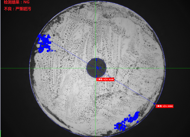
-
Automated production and quality inspection: This is the area where industrial cameras are most extensively used. For example, in electronics manufacturing, they are responsible for checking whether chip pins are flush and whether there are any cold solder joints; on automotive production lines, they rapidly measure key dimensions of components and identify defects such as surface scratches, dents and burrs; in the food and beverage industry, they check the liquid level in bottles, the integrity of bottle caps, and whether the inkjet codes on packaging surfaces are correct.
-
Guidance and Positioning: Industrial cameras work in conjunction with robots to enable high-precision gripping, assembly and handling. They provide real-time feedback to robotic arms on ‘where a part is’ and ‘by how much it is misaligned’, endowing automated equipment with hand-eye coordination capabilities.
-
Visual Navigation: On unmanned logistics vehicles and intelligent warehouse AGVs (Automated Guided Vehicles), industrial cameras are used to recognise QR codes, colour bands or natural road surface features, enabling the vehicles to navigate precisely and avoid obstacles in complex environments.
-
Other Applications: Medical image analysis, microscopic imaging in scientific experiments, and inspections of railways and power grids are all reliant on these tireless ‘electronic eyes’.
IV. Practical Approaches to Combining Schemes
An industrial camera is merely an ‘eye’; to be truly effective, it must be integrated with a lens, lighting, and image acquisition and processing software to form a complete vision system. When putting together a solution, the following aspects should be considered.
1. First, clarify ‘what to look at’ and ‘what to do’
Define the inspection targets and required accuracy; for example, whether the smallest defect to be detected is 0.1 millimetres, or whether only centimetre-scale features need to be distinguished; whether the objective is measurement, counting, colour recognition or positioning. This directly determines the camera’s resolution and colour type. Next, confirm whether the object being inspected is moving or stationary, and at what speed, in order to select the appropriate shutter mode and frame rate. Generally speaking, high-speed production lines require a global shutter camera capable of capturing tens or even hundreds of frames per second.
2. Once the camera has been selected, pair it with a suitable lens
The lens and camera must have compatible mounts (commonly C or CS mounts), and the lens’s image circle must cover the size of the camera’s sensor; otherwise, dark corners will occur. The focal length is calculated based on the working distance and field of view. When measuring small, high-precision parts, a telecentric lens with extremely low distortion is often required. If multiple surfaces need to be captured simultaneously at a single workstation, a multi-camera synchronised triggering solution can also be used.
3. Selecting the appropriate lighting for high-quality images
Lighting is often the key factor determining the success or failure of the entire solution. Use backlighting to highlight edges; use low-angle ring lighting to eliminate reflections and reveal surface scratches; and use coaxial or dome lighting to emphasise uneven characters. For colour inspection, select a white light source or coloured light of a specific wavelength to enhance contrast. The stability of the light source is also of the utmost importance; it must be paired with a controller for constant-current or stroboscopic drive.
4. Determining Image Transmission and Processing
Depending on the data volume, transmission distance and host interface, select a suitable acquisition card or connect a camera with a GigE/USB 3.0 interface directly to an industrial PC. Once the host computer software has acquired the images, it utilises pre-configured algorithmic tools to perform defect detection, dimensional calculations, character recognition and other tasks. Nowadays, much processing software has been modularised and supports no-code development, making solution implementation more flexible.
Selection Example:
For example, consider the task of detecting minute surface scratches on gears. The requirements are: stationary inspection, an accuracy of 0.05 millimetres, and the ability to identify the location of the defects. This can be achieved by combining a 5-megapixel monochrome area-scan camera with a high-resolution fixed-focus lens, using a low-angle annular white light source, and connecting the camera to an industrial PC via a USB 3.0 interface. The light source illuminates the surface from the side; areas with impact damage produce diffuse reflection, appearing as bright spots, whilst undamaged surfaces remain dark. The software can then quickly pinpoint defects through greyscale analysis.
Product recommendation
TECHNICAL SOLUTION
MORE+You may also be interested in the following information
FREE CONSULTING SERVICE
Let’s help you to find the right solution for your project!
 ASK POMEAS
  PRICE INQUIRY
  REQUEST DEMO/TEST
  FREE TRIAL UNIT
  ACCURATE SELECTION
- APPICATION CASE
- RESOURCE CENTER
- DOWNLOAD CENTER
SOLUTIONS SUPPORT
- ZOOM LENS SELECTION TOOL
- TELECENTRIC LENS SELECTION TOOL
- FA LENS SELECTION TOOL
- ZOOM RATIO TABLE
- CERTIFIED MODEL
SELECTION TOOL
- WHY POMEAS
- FAQ
- PRIVACY POLICY
- TERMS OF USE
- DELIVERY & RETURN POLICY
CUSTOMER CARE
 ADDRESS
Add.:No.68, Yongwei Road, Baizhoubian, Dongcheng District, Dongguan, China,523000
CONTACT
 Tel:+ 86-0769-2266 0867
 Fax:+ 86-0769-2266 0867
 E-mail:marketing@pomeas.com

Wechat QR code

Software Copyright :2021SR0176001 抄袭必究, 技术支持:誉新源科技