


Image measuring instrument: Dial gauge measurement of minute components
Test Object

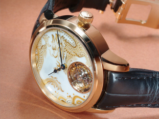
Core components of a watch movement, such as the main plate, escape wheel, balance wheel and small plate. These components are minute in size and feature complex geometric characteristics, including systems of holes, stepped surfaces, curved contours and narrow annular grooves; they are typical examples of high-value, micro-precision metal components.
Testing Requirements

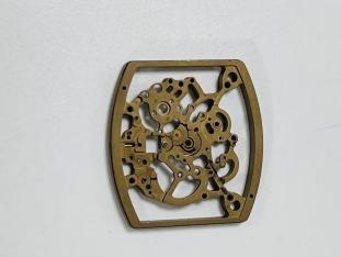
Each individual component requires inspection of over 300 dimensional parameters, including length, width, circularity, curvature, height and positional accuracy. With a precision grade of 0.01 mm, the real challenge lies not in achieving extreme resolution, but in ensuring measurement stability within a high-volume production environment—where continuous, repeated measurements of the same feature must be highly consistent, with no drift or sporadic fluctuations permitted, in order to prevent misjudgement and scrapping of high-value components.
Testing Protocol

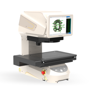
Utilising the high-precision Image 3 Pro-H imaging measuring system as the core platform, with a spectral confocal sensor integrated along the Z-axis, this solution achieves the integration of two-dimensional imaging measurement and three-dimensional non-contact height inspection. To address the challenges of small parts tending to tilt during clamping and the difficulty in establishing a uniform reference, a set of precision fixtures has been specifically designed. The jig’s base plate has been ground to achieve exceptional flatness, providing a measurement reference surface that is perfectly aligned with the part’s design reference. Once the part is placed on the jig, it is held in position by its own weight or by a flexible clamping plate, thereby eliminating clamping errors at source and ensuring that measurements of related dimensions—such as height and positional accuracy—are based on a unified reference.
Testing Process
1. Clamping and positioning: The operator places the part into the fixture and gently pushes it until it is flush against the reference surface; no manual focusing or levelling is required.
2. Programme initiation: A pre-set automated measurement programme is called up, and the equipment immediately enters fully automatic operation mode.
3. Composite Measurement Execution: Firstly, the image measurement system automatically focuses and captures the part’s edges, extracting two-dimensional contour parameters such as length, width, hole diameter, roundness and arc radius in a single scan; subsequently, the spectral confocal probe moves along the programmed path to rapidly acquire point-by-point measurements of features such as step height, hole depth and boss height. The probe’s spot size is minute, allowing it to penetrate microstructures without damaging the part’s surface.
4. Data Fusion and Reporting: The measurement software fuses the two-dimensional coordinates with the height data into a single spatial coordinate system, automatically calculating spatial dimensions such as positional accuracy and completing the evaluation of all 300-plus parameters. Results are displayed in real time with green/red indicators to distinguish between compliant and out-of-tolerance items, and a comprehensive inspection report is generated.
5. Stable Output: The entire measurement process requires no human intervention. The unified reference of the fixture, combined with hardware compensation within the equipment, ensures that the variation in repeated measurements at the same point is far smaller than the tolerance band. This fully meets the requirements for stable measurement at the 0.01 mm level and effectively supports high-quality quality control for large-volume production of watch movement components.
Product recommendation
TECHNICAL SOLUTION
MORE+You may also be interested in the following information
FREE CONSULTING SERVICE
Let’s help you to find the right solution for your project!
 ASK POMEAS
  PRICE INQUIRY
  REQUEST DEMO/TEST
  FREE TRIAL UNIT
  ACCURATE SELECTION
- APPICATION CASE
- RESOURCE CENTER
- DOWNLOAD CENTER
SOLUTIONS SUPPORT
- ZOOM LENS SELECTION TOOL
- TELECENTRIC LENS SELECTION TOOL
- FA LENS SELECTION TOOL
- ZOOM RATIO TABLE
- CERTIFIED MODEL
SELECTION TOOL
- WHY POMEAS
- FAQ
- PRIVACY POLICY
- TERMS OF USE
- DELIVERY & RETURN POLICY
CUSTOMER CARE
 ADDRESS
Add.:No.68, Yongwei Road, Baizhoubian, Dongcheng District, Dongguan, China,523000
CONTACT
 Tel:+ 86-0769-2266 0867
 Fax:+ 86-0769-2266 0867
 E-mail:marketing@pomeas.com

Wechat QR code

Software Copyright :2021SR0176001 抄袭必究, 技术支持:誉新源科技