


3D Inspection Solution for Gears: Precise Flatness Measurement and Front/Back Identification
In the field of precision manufacturing, gears serve as core components in mechanical transmission systems, and their quality directly impacts the operational efficiency and stability of the entire system. To address the inspection requirements for metal gear components, we have designed a highly efficient and accurate 3D inspection solution aimed at simultaneously enabling precise measurement of gear surface flatness and rapid differentiation between the front and back surfaces.
Overview of the Testing Protocol
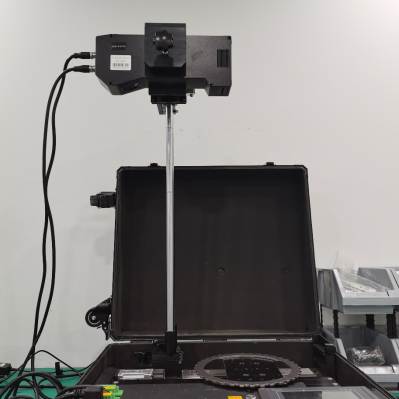
The solution is based on advanced machine vision technology. It uses POMEAS’s proprietary 3D line laser profile sensor and high-precision cameras to perform non-contact scanning of gears. By combining image processing with 3D reconstruction algorithms, it enables quantitative assessment of gear surface flatness and intelligent identification of the front and back sides.
Flatness Inspection Solution
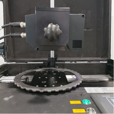
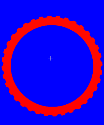
1. Positioning and Scanning: First, image processing technology is used to capture the coordinates of the gear’s inner circle as a positioning reference, ensuring that the starting position remains consistent for each scan. The camera then scans the entire surface of the gear at a constant speed of 100 mm/s from above, covering all key measurement points.
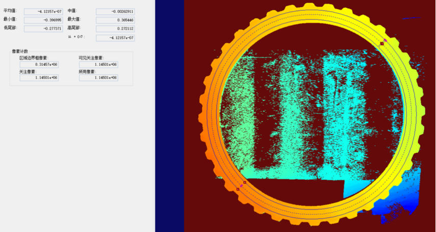
2. Data Processing and Flatness Calculation: Using advanced image processing algorithms, the gear surface is identified and a reference plane is fitted. The height difference between each point on the gear surface and this reference plane is calculated. The flatness data of the gear surface is then derived by statistically analyzing the difference between the highest and lowest values. This method effectively eliminates the influence of local outliers, thereby improving measurement accuracy.
Front and Back Identification Scheme

1. Image preprocessing: The captured gear images are processed to convert them to grayscale, enhancing edge features to facilitate subsequent template alignment and contour extraction.
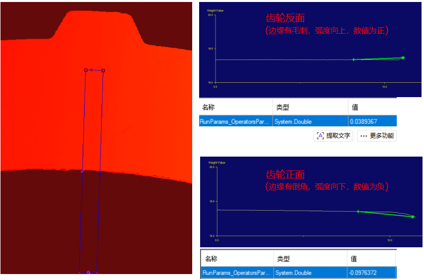
2. Template Alignment and Contour Extraction: The protruding outer portion of the gear is captured as a template, and template matching technology is used to quickly align the gear. Subsequently, a 3D cross-section tool is used to obtain the gear’s cross-sectional contour, providing the basis for subsequent curvature calculations.
3. Curvature Calculation and Front/Back Determination: Based on the extracted contour data, the direction of the edge curvature is calculated. According to preset rules, the curvature of the front edge is negative, while that of the back edge is positive, thereby accurately distinguishing between the front and back sides of the gear.
Advantages of the Solution
1. Non-contact measurement: This method avoids the potential damage associated with traditional contact-based measurement, thereby protecting the surface quality of the gears.
2. High precision and efficiency: By combining advanced image processing and 3D reconstruction algorithms, it enables fast and accurate measurement and identification.
3. Intelligent operation: With a high degree of automation, it reduces manual intervention and improves the consistency and reliability of inspections.
4. High adaptability: Capable of meeting inspection requirements for gears of various sizes and shapes, offering broad applicability.
Product recommendation
TECHNICAL SOLUTION
MORE+You may also be interested in the following information
FREE CONSULTING SERVICE
Let’s help you to find the right solution for your project!

 ASK POMEAS
  PRICE INQUIRY
  REQUEST DEMO/TEST
  FREE TRIAL UNIT
  ACCURATE SELECTION
 - APPICATION CASE
- RESOURCE CENTER
- DOWNLOAD CENTER
SOLUTIONS SUPPORT
- ZOOM LENS SELECTION TOOL
- TELECENTRIC LENS SELECTION TOOL
- FA LENS SELECTION TOOL
- ZOOM RATIO TABLE
- CERTIFIED MODEL
SELECTION TOOL
- WHY POMEAS
- FAQ
- PRIVACY POLICY
- TERMS OF USE
- DELIVERY & RETURN POLICY
CUSTOMER CARE
 ADDRESS
Add.:No.68, Yongwei Road, Baizhoubian, Dongcheng District, Dongguan, China,523000
CONTACT
 Tel:+ 86-0769-2266 0867
 Fax:+ 86-0769-2266 0867
 E-mail:marketing@pomeas.com

Wechat QR code
Software Copyright :2021SR0176001 抄袭必究, 技术支持:誉新源科技