


What technical specifications should be considered when selecting a line-scan lens?
Line-scan lenses are a critical component of line-scan industrial camera imaging systems. Compared to common area-scan lenses, line-scan camera sensors are typically elongated and capture a full image by coordinating with the relative motion of the object being measured. Therefore, when selecting a lens, one must not only consider focal length and mount type but also take into account factors such as image plane coverage, resolution matching, depth of field, lighting conditions, distortion, and mechanical mounting.

I. Determine the Field of View, Sensor Cable Length, and Magnification First
The first step in selecting a line-scan lens is to determine the width of the field of view (FOV) to be imaged and the line length of the camera sensor. The optical magnification of a lens is generally defined as the ratio of the sensor’s line length to the FOV width. In other words, once the sensor is specified, the wider the desired FOV, the lower the required magnification; conversely, to resolve finer features, a higher magnification is needed. When selecting a lens, ensure that the lens’s image plane covers the effective imaging area of the camera sensor, leaving some margin to avoid a decline in image quality at the edges or obstruction. Although line-scan sensors are narrow in width, they are long in the longitudinal direction; therefore, the diameter of the lens’s image plane, edge illuminance, and edge resolution must all be carefully verified.

II. Resolution and MTF: It’s Not Just About Pixel Count
Line-scan cameras are often described in terms of pixel size, line rate, and resolution, but the optical resolution of the lens itself is equally critical. When selecting a lens, attention should be paid to its MTF performance at the corresponding spatial frequencies, particularly the contrast near the camera’s pixel size and the Nyquist frequency. Simply put, no matter how small the camera’s pixels are, if the lens cannot clearly transmit details to the image plane, the overall resolution of the system will be limited. For line-scan applications, the MTF at the edges of the field of view is equally important, as the ends of the long, narrow sensor are prone to becoming areas of poor image quality. It is recommended to verify performance through actual shooting tests using resolution test charts, rather than relying solely on the lens’s nominal specifications.
III. Working Distance and Depth of Field
Working distance refers to the distance from the front of the lens to the surface of the object being measured, which must be determined based on the available space, light source installation, and motion mechanisms. Line-scan lenses are typically designed with a fixed focal length or fixed magnification; changes in working distance will affect both the magnification and image sharpness. Depth of field, on the other hand, determines the range within which the image remains in focus even when the height of the object being measured fluctuates. Depth of field is related to the aperture, magnification, and the permissible circle of diffusion: the higher the magnification, the shallower the depth of field tends to be; reducing the aperture increases the depth of field, but an aperture that is too small can lead to diffraction effects and a decrease in brightness. Therefore, one cannot simply assume that a smaller aperture is always better; instead, a balance must be struck between brightness, depth of field, and resolution.
IV. Aperture and Relative Illuminance
The aperture affects light intake, depth of field, and diffraction behavior. When line-scan cameras operate at high frame rates, exposure times are often short, requiring sufficient illumination and lens light transmission capability. If the aperture is set wide, brightness increases but the depth of field becomes shallower; if the aperture is set too narrow, edge illumination decreases and diffraction issues may become more pronounced. Relative illuminance reflects the variation in brightness at the edges of the image plane relative to the center; for line-scan lenses, particular attention must be paid to illuminance performance at both ends along the length of the image. Darker edges directly affect threshold determination, defect detection, and color consistency; if necessary, this can be improved through light source compensation or by selecting a lens with a larger image field of view.
V. Interfaces, Flange Distance, and Back Focus Distance
The lens mount must be compatible with the camera mount; common types include M42, M58, and F-mount. In addition to thread or bayonet mounts, you must also verify the flange focal distance, back focal length, and potential mechanical interference. Some line-scan cameras have larger mounts, and the rear of the lens or an adapter ring may protrude into the camera body; if the back focal length is insufficient, this may affect installation. When selecting a lens, verify the lens’s external dimensions, rear diameter, locking mechanism, and the depth of the camera mount to avoid situations where the lens cannot be mounted upon delivery.
VI. Spectra and Color Difference
Line-scan systems are often used with line light sources, which may emit white light, red light, blue light, infrared light, or other monochromatic light. Lens coatings and chromatic aberration correction are typically designed for specific wavelength bands. If the actual light source wavelength does not match the lens’s operating range, this may result in reduced transmittance, focal shift, or peripheral chromatic aberration. When using monochromatic light, focus on the lens’s imaging performance within that specific wavelength band; when using white light and color accuracy is critical, prioritize the lens’s achromatic correction capabilities and consistency in color reproduction.
VII. Distortion and Aperture Correction
Distortion, which includes barrel distortion and pincushion distortion, can affect dimensional measurements and position determination. For general inspection applications, it is sufficient to focus on TV distortion or overall distortion levels; however, for precision measurement applications, greater emphasis should be placed on low-distortion designs. If the object being measured varies in height, the magnification of a standard lens may change with the object distance, leading to unstable measurement results. Object-side telecentric lenses maintain a relatively stable magnification within a certain depth of field, making them suitable for dimensional measurement and hole position inspection; however, they are typically larger, heavier, and more expensive, so selection should be based on actual requirements.
VIII. Mechanical Dimensions, Environment, and Motion Synchronization
Line-scan lenses are often mounted on motion platforms or near production lines; the lens’s weight, length, locking mechanism, and vibration resistance can affect long-term stability. Changes in ambient temperature may cause focus drift, while dust and oil can affect lens transmittance; protective enclosures should be considered when necessary. Line-scan imaging is also related to motion speed, line rate, and exposure time: excessively long exposure times can cause motion blur, while insufficient exposure affects the signal-to-noise ratio. Lens selection should be evaluated in conjunction with the camera’s line frequency, light source brightness, and motion speed.
IX. Recommended Model Selection and Validation Process
When selecting a lens, first determine the magnification based on the field of view and sensor cable length, then determine the working distance based on the installation space, and subsequently verify the image plane coverage, interface, and back focal length. Next, evaluate the lens’s MTF and resolution based on pixel size and detection accuracy requirements, and then select the aperture range based on the light source wavelength, depth of field requirements, and exposure conditions. Finally, conduct practical tests using resolution charts, distortion grids, edge illuminance samples, and samples with varying heights to confirm that the image quality at the center and edges is consistent. For measurement-related projects, you should also verify the stability of the magnification and the degree of telecentricity.
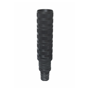
Product recommendation

TECHNICAL SOLUTION
MORE+You may also be interested in the following information


FREE CONSULTING SERVICE
Let’s help you to find the right solution for your project!
 ASK POMEAS
 PRICE INQUIRY
 REQUEST DEMO/TEST
 FREE TRIAL UNIT
 ACCURATE SELECTION

- APPICATION CASE
- RESOURCE CENTER
- DOWNLOAD CENTER
SOLUTIONS SUPPORT
- ZOOM LENS SELECTION TOOL
- TELECENTRIC LENS SELECTION TOOL
- FA LENS SELECTION TOOL
- ZOOM RATIO TABLE
- CERTIFIED MODEL
SELECTION TOOL
- WHY POMEAS
- FAQ
- PRIVACY POLICY
- TERMS OF USE
- DELIVERY & RETURN POLICY
CUSTOMER CARE
 ADDRESS
Add.:No.68, Yongwei Road, Baizhoubian, Dongcheng District, Dongguan, China,523000
CONTACT
 Tel:+ 86-0769-2266 0867
 Fax:+ 86-0769-2266 0867
 E-mail:marketing@pomeas.com

Wechat QR code

Software Copyright :2021SR0176001 抄袭必究, 技术支持:誉新源科技