


The principle is based on classical triangulation. The sensor actively emits an extremely fine laser beam onto the surface of the target, whilst a built-in camera captures the distortion of this laser beam caused by surface irregularities from a specific angle. By detecting changes in the position of the reflected spot, the height of the object’s contour can be calculated, thereby generating three-dimensional surface data.

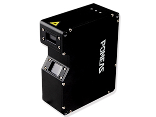
Triangulation: A Ruler Made of Light
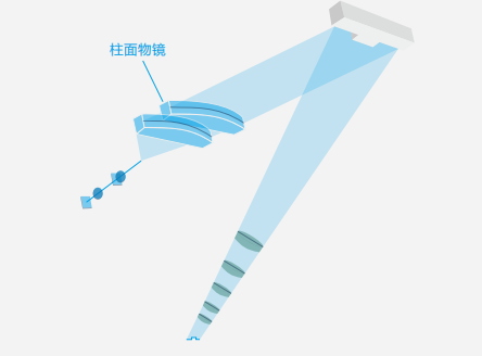
You can imagine the interior of the sensor as a fixed geometric layout. At one end is a laser emitter, which emits a laser beam at a specific angle; at the other end is a high-resolution camera, which observes the illuminated surface from a different angle.
When the height of an object’s surface changes, the position of the laser spot as seen by the camera shifts. This shift forms a stable triangular relationship with the change in height. Inside the sensor, the distance between the laser and the camera (the baseline) is fixed and known, and the number of pixels by which the spot captured by the camera has moved can also be quantified. Using simple trigonometric formulas, the height of each point can be calculated with precision. This non-contact optical ranging method lies at the heart of the entire technology.
From Point to Line: A Comprehensive View of the Entire Cross-Section
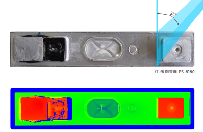
If only a single laser spot is emitted, the height of only one point can be measured at a time. The ingenuity of a line laser sensor lies in the fact that an optical lens stretches the laser beam into a laser line consisting of countless densely packed light points.
When this line is projected onto the surface of an object, it is effectively conducting a ‘height survey’ of tens of thousands of points along the line simultaneously. In concave areas, the laser stripes in the camera curve downwards; in convex areas, they arch upwards. The camera rapidly captures an image of this distorted laser line, and the internal processor immediately applies algorithms to precisely determine the centre position of every illuminated area along the stripes. By converting these pixel coordinates into actual heights, the object’s profile along this cross-section—such as the height difference of a step or the curvature of a curved surface—is instantly digitised, generating a two-dimensional contour line.
From Lines to Surfaces: Assembling Slices into a 3D Model

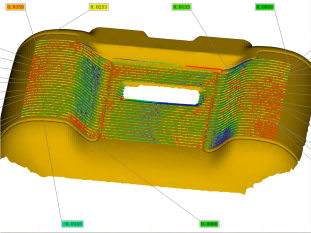
If only a single cross-section is obtained from a single scan, how can a complete three-dimensional contour be derived? The answer lies in incorporating motion.
On a production line, sensors are typically fixed in place whilst the object under test moves at a constant speed along a conveyor belt; alternatively, a robotic arm may hold the sensor and sweep it across the object’s surface. Much like scanning a document, the sensor continuously captures contour lines at a rate of several thousand times per second, whilst simultaneously recording the distance travelled for each frame. By stitching these dense contour lines together in their actual spatial sequence, a complete 3D point cloud model is constructed. This process is equivalent to using a ‘light knife’ to slice the object into sections for scanning, before reassembling them into a single entity in the digital world.
Product recommendation
TECHNICAL SOLUTION
MORE+You may also be interested in the following information
FREE CONSULTING SERVICE
Let’s help you to find the right solution for your project!

 ASK POMEAS
  PRICE INQUIRY
  REQUEST DEMO/TEST
  FREE TRIAL UNIT
  ACCURATE SELECTION
- APPICATION CASE
- RESOURCE CENTER
- DOWNLOAD CENTER
SOLUTIONS SUPPORT
- ZOOM LENS SELECTION TOOL
- TELECENTRIC LENS SELECTION TOOL
- FA LENS SELECTION TOOL
- ZOOM RATIO TABLE
- CERTIFIED MODEL
SELECTION TOOL
- WHY POMEAS
- FAQ
- PRIVACY POLICY
- TERMS OF USE
- DELIVERY & RETURN POLICY
CUSTOMER CARE
 ADDRESS
Add.:No.68, Yongwei Road, Baizhoubian, Dongcheng District, Dongguan, China,523000
CONTACT
 Tel:+ 86-0769-2266 0867
 Fax:+ 86-0769-2266 0867
 E-mail:marketing@pomeas.com

Wechat QR code

Software Copyright :2021SR0176001 抄袭必究, 技术支持:誉新源科技