


Image Measurement Systems in Mobile Phone Accessory Inspection Applications
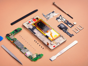
The mobile phone accessories industry is characterized by high-volume production, strict precision requirements, and rapid product iteration. From pilot production to mass production, the time window allocated for the inspection phase of a phone case is often only a few days. When using traditional calipers and micrometers to inspect curved surfaces, irregularly shaped holes, and tiny buttons, it is difficult to balance both efficiency and quality. In such scenarios, image measuring systems have gradually become standard equipment on production lines. The following real-world example illustrates their primary applications.

Case Background: Inspection Bottlenecks at a Mobile Phone Accessories Factory

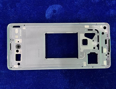
A mobile phone accessory supplier in South China received a bulk order for mid-frames and side buttons from a certain brand. The mid-frames feature more than ten irregularly shaped holes and multiple curved transition surfaces, while the buttons are small, irregularly shaped parts with tolerance requirements generally within ±0.02 mm. Previously, traditional measuring tools were used for spot checks, but performing full-dimension inspections on individual parts was time-consuming. Furthermore, the positional accuracy of curved surfaces and holes relied on manual alignment, resulting in inconsistent results among different inspectors. During the trial production phase, uneven gaps were observed after assembling the casing with the screen. Investigation revealed that the positional accuracy of certain holes was out of tolerance, but traditional spot checks had failed to detect this issue in a timely manner.
Specific Applications of Image Measurement Systems on Production Lines

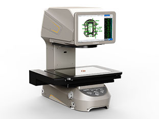
After introducing the image measurement system, the factory deployed it in two stages—trial production verification and mass production spot checks—where it primarily performs the following types of inspection tasks:
First, inspection of the housing contour and hole dimensions. The mid-frame housing is placed on the measurement platform, where the equipment captures an overall image using a high-resolution lens. The software automatically identifies the outer contour boundaries and the edge positions of each hole, outputting dimensional data—such as length, width, hole diameter, hole spacing, and positional accuracy—in a single operation. For curved transition surfaces, the system performs multi-point fitting along the contour to evaluate whether the arc radius and contour profile fall within the tolerance band. Tasks that previously required multiple setups and individual measurements can now be completed with a single image capture.
Second is the verification of flatness dimensions and geometric tolerances for screen accessories. Accessories such as screen covers and foam spacers are sensitive to flatness and contour accuracy. By comparing deviations between the standard contour and the actual contour, the image measuring instrument quickly determines the compatibility of accessories with screen modules, preventing issues such as bright edges or uneven gaps caused by dimensional deviations after assembly.
Third, batch sampling inspection of small button-type components. Side buttons are small and irregularly shaped, making them difficult to clamp securely with traditional gauges. Image measurement systems use a non-contact method; after placement, they automatically recognize the button’s contour, length, width, and key fillet radii, significantly shortening the measurement cycle per piece and making them suitable for batch sampling scenarios. Multiple pieces from the same batch can be arranged sequentially, and the software identifies and records data for each piece individually, reducing variations caused by manual alignment.
Fourth, tolerance verification and issue tracing during the pilot production phase. During pilot production, samples of the housing, screen components, and buttons are measured separately, and the actual measured dimensions are compared with the nominal CAD values to quickly identify out-of-tolerance items. In the case mentioned above, it was precisely through the full-dimension scan performed by the image measuring instrument that a deviation in the positional accuracy of a specific hole was discovered; after adjusting the mold, the assembly gap issue was resolved.
Performance and Limitations of Use

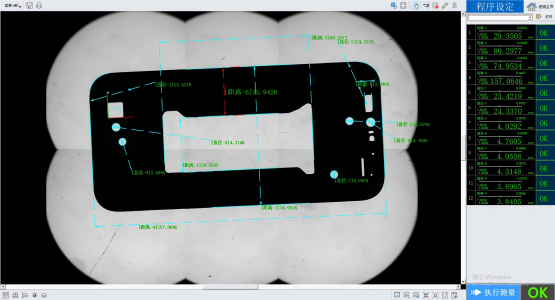
According to customer feedback, image measuring systems offer significant advantages in batch inspections with high repeatability requirements: non-contact measurement prevents deformation of thin-walled parts caused by applied forces; the software’s automatic edge detection reduces human-induced alignment errors; and measurement data can be exported for trend analysis.
It should be noted that image-based measuring instruments are primarily suitable for two-dimensional planar dimensional and contour inspection; for three-dimensional features in the depth direction, other methods are still required. Additionally, surface reflections, oil contamination, or tilted placement of workpieces can affect image quality, so workpieces must be kept clean and positioned consistently when used on production lines.
Product recommendation
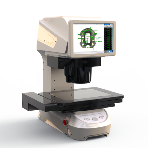


TECHNICAL SOLUTION
MORE+You may also be interested in the following information
FREE CONSULTING SERVICE
Let’s help you to find the right solution for your project!
 ASK POMEAS
 PRICE INQUIRY
 REQUEST DEMO/TEST
 FREE TRIAL UNIT
 ACCURATE SELECTION

- APPICATION CASE
- RESOURCE CENTER
- DOWNLOAD CENTER
SOLUTIONS SUPPORT
- ZOOM LENS SELECTION TOOL
- TELECENTRIC LENS SELECTION TOOL
- FA LENS SELECTION TOOL
- ZOOM RATIO TABLE
- CERTIFIED MODEL
SELECTION TOOL
- WHY POMEAS
- FAQ
- PRIVACY POLICY
- TERMS OF USE
- DELIVERY & RETURN POLICY
CUSTOMER CARE
 ADDRESS
Add.:No.68, Yongwei Road, Baizhoubian, Dongcheng District, Dongguan, China,523000
CONTACT
 Tel:+ 86-0769-2266 0867
 Fax:+ 86-0769-2266 0867
 E-mail:marketing@pomeas.com

Wechat QR code

Software Copyright :2021SR0176001 抄袭必究, 技术支持:誉新源科技